Introdução
Os materiais plásticos em geral são excelentes isolantes. Devido à sua alta resistência mecânica e ao seu baixo peso, eles são particularmente adequados para o mercado elétrico e eletrônico (E&E), bem como para os setores de transporte e eletrodomésticos. Um material plástico comumente usado para essas aplicações é da família da poliamida: O PA6, que apresenta boa qualidade de superfície, capacidade de processamento e preços ligeiramente mais baixos do que outros PAs, é especialmente adequado. Em muitas dessas aplicações, o material plástico é reforçado com fibras de vidro curtas para melhorar ainda mais o desempenho mecânico.
No entanto, esses materiais podem se incendiar quando estiverem próximos o suficiente de uma fonte de ignição, como uma faísca elétrica. Uma medida comum para garantir a segurança contra incêndios é a adição de retardadores de chama (FR). O tipo e a quantidade de retardante de chamas usados dependem da aplicação e dos requisitos associados estabelecidos por vários padrões de inflamabilidade.
Em geral, deseja-se uma baixa quantidade de retardante de chamas para ter o menor efeito sobre as propriedades do plástico e o comportamento do processamento. Como qualquer aditivo, os retardadores de chama aumentam a viscosidade dos polímeros fundidos, o que é especialmente importante no setor de eletrônicos, no qual a miniaturização e, portanto, paredes muito finas são padrão. Existe uma variedade de retardantes de chamas para o PA6.
Os incêndios iniciados até mesmo por uma única faísca elétrica geram fumaça desde o início. É por isso que a maioria das vítimas de incêndios morre devido à fumaça tóxica. Além disso, a fumaça pode ficar densa o suficiente para dificultar a orientação visual ou até mesmo obstruir a fuga de uma pessoa presa. As substâncias corrosivas presentes na fumaça também podem danificar equipamentos que não seriam afetados pelo incêndio. A toxicidade e a corrosividade frequentemente observadas são provenientes de polímeros halogenados ou retardadores de chama. Por esse motivo, retardantes de chama especiais não halogenados e retardantes de chama à base de grafite são usados para evitar esses problemas.
Condições de medição
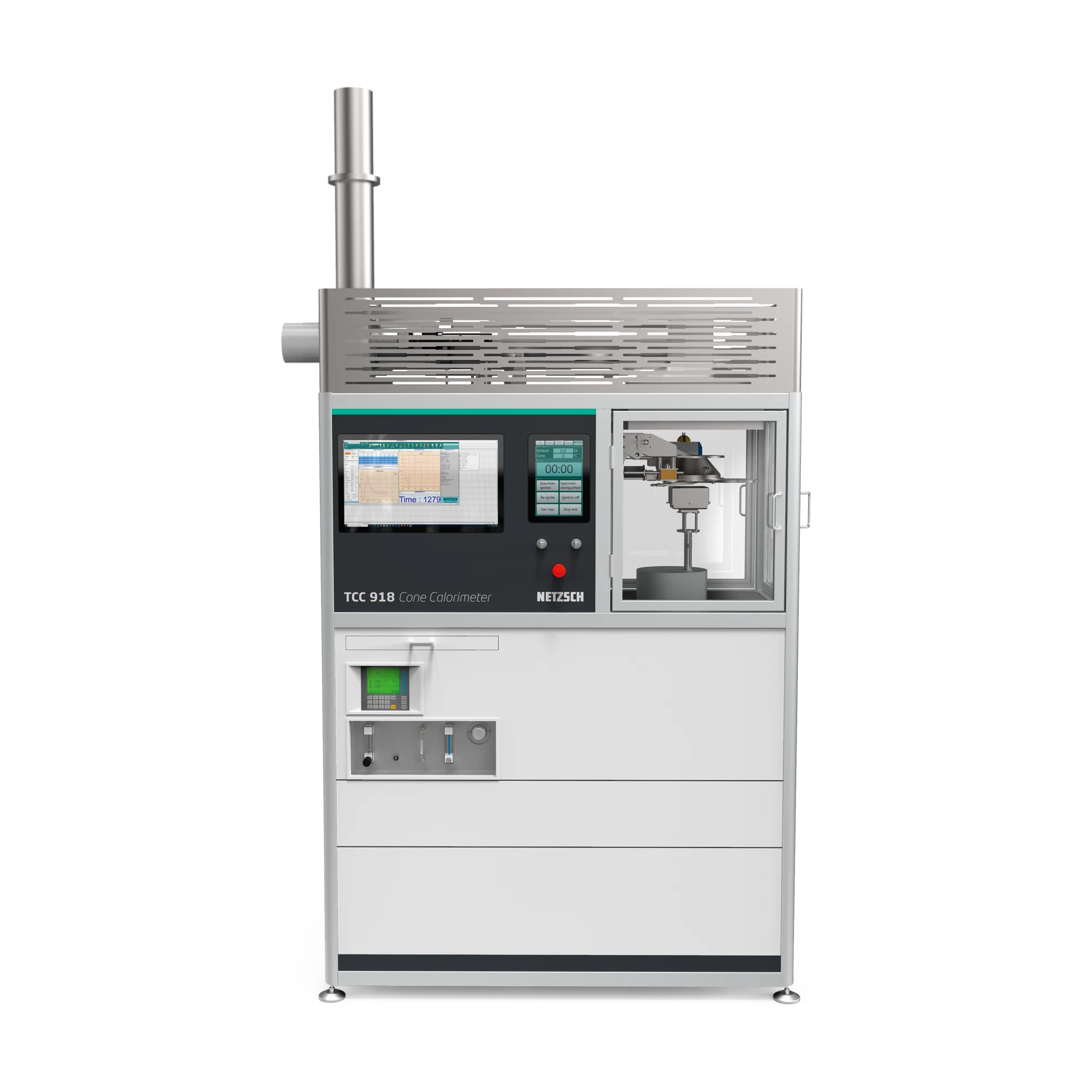
Para destacar o efeito de diferentes retardadores de chama não halogenados no comportamento de fogo do PA6, amostras dos diferentes compostos foram moldadas por injeção em placas de 100 x 100 x 4 mm3 e testadas no TCC 918 (figura 1). O instrumento permite a determinação da liberação de calor, da perda de massa, da DensidadeA densidade de massa é definida como a relação entre massa e volume. densidade e da composição do gás de fumaça. As amostras foram posicionadas em um suporte de amostra horizontal que é colocado na célula de carga. A célula de carga monitora a massa da amostra durante a medição. Um aquecedor elétrico radiante cônico irradia uniformemente a amostra a partir da parte superior. Um dispositivo de ignição de faísca está localizado entre a superfície da amostra e o aquecedor cônico. Isso inflama os gases inflamáveis que saem da amostra quando ela é aquecida. Os gases de combustão produzidos passam pelo cone de aquecimento e são coletados por um sistema de duto de exaustão com um ventilador centrífugo e um exaustor. Na seção de medição do duto de exaustão, o fluxo de massa e a temperatura do gás de fumaça podem ser medidos, bem como as concentrações deO2,CO2 e CO e a transmissão de luz laser através do gás de fumaça.
libralibraAntes de iniciar os testes, o sistema de análise de gás (Siemens Oxymat/Ultramat) foi abastecido com gases de combustão e o fator C foi verificado com o uso do queimador de metano com uma liberação de calor definida. O analisador de gás usado foi equipado comO2 e uma opção deCO2. Após o aquecimento do aquecedor de cone, o obturador foi fechado e o suporte de amostra preparado foi posicionado na placa de aterramento. Em seguida, o sistema removeu automaticamente o obturador para o início da medição. Os gases evaporados foram inflamados pelo sistema de ignição automática. As condições de medição estão resumidas na tabela 1.
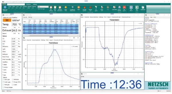
A Figura 2 mostra os resultados da medição no PA 6 puro e a visualização no software TCC. A coluna da esquerda mostra os dados de entrada da medição; no meio, uma tabela com os valores medidos de 751 a 756 s pode ser vista junto com dois exemplos de gráficos dos dados medidos; e a coluna da direita apresenta uma visão geral dos valores da análise selected para essa medição específica.
Tabela 1: Condições de medição
| Suporte de amostra | Horizontal | |
| Fluxo de calor | 50 kW/m² | |
| Taxa de fluxo nominal do duto | 24.0 l/s | |
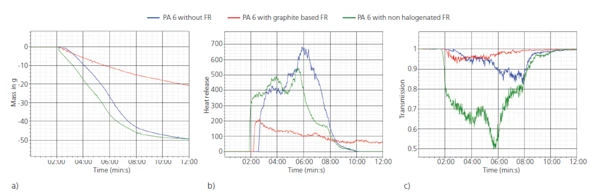
A Figura 3 permite uma análise mais detalhada dos resultados. A Figura 3a mostra a perda de massa, b) mostra a taxa de liberação de calor e c) mostra a transmissão em função do tempo para as três amostras diferentes. É possível observar que a amostra de PA6 com 20 wt% de retardante de chamas à base de grafite (curva vermelha) apresenta a menor perda de massa, liberação de calor e liberação de fumaça (menor redução na transmissão) de todas as amostras. Em comparação, a amostra com 20 wt% de retardante de chamas não halogenado (curva verde) se comporta de forma muito semelhante ao material PA6 puro (curva azul). No que diz respeito à liberação de calor, ela apresenta valores ligeiramente mais baixos e também a liberação de calor termina mais cedo. No entanto, no que diz respeito à transmissão, a emissão de fumaça é muito maior do que a do PA6 puro.
Resumo
Essas investigações mostram que, no caso desse PA6 específico, bem como das cargas de FR investigadas, o retardante de chamas à base de grafite tem um desempenho muito melhor e reduz significativamente os efeitos prejudiciais que um incêndio pode ter em seus arredores. No caso do FR não halogenado, cargas adicionais precisariam ser estudadas para identificar uma composição com melhor desempenho.