Introduction
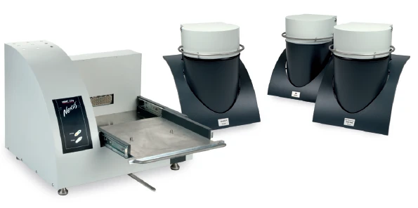
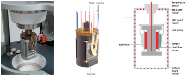
The NETZSCH Calorímetro de Múltiplo Módulo (MMC)A multiple mode calorimeter device consisting of a base unit and exchangeable modules. One module is prepared for accelerating rate calorimetry (ARC), the ARC-Module. A second one is used for scanning tests (Scanning Module) and a third one is related to battery testing for coin cells (Coin Cell Module).Multiple Module Calorimeter (MMC) 274 Nexus® (figure 1) offers three different measurement modules. The Calorimetria por taxa de Aceleração (ARC)The method describing isothermal and adiabatic test procedures used to detect thermally exothermic decomposition reactions.ARC® Module can be used for so-called heat-wait-search (Calor – Esperar – PesquisaHeat-Wait-Search is a measurement mode used in calorimeter devices according to accelerating rate calorimetry (ARC).HWS) tests or Thermal runawayA thermal runaway is the situation where a chemical reactor is out of control with respect to temperature and/or pressure production caused by the chemical reaction itself. Simulation of a thermal runaway is usually carried out using a calorimeter device according to accelerated rate calorimetry (ARC).thermal runaway tests [1][2]; the Scanning ModuleA calorimeter module being part of the Multipe Module Calorimeter (MMC) allowing for scanning test of a sample. This procedure can serve as a screening test in order to detect a thermal hazard potential within a reasonably short measurement time.Scanning Module is suited for such applications as the evaluation of endothermic or exothermic Phase TransitionsThe term phase transition (or phase change) is most commonly used to describe transitions between the solid, liquid and gaseous states.phase transitions as well as thermal hazard screening [3][4]; and the Módulo de Célula tipo moedaA calorimeter module being part of the Multiple Module Calorimeter (MMC) allowing for scanning and isothermal tests of complete coins of variable size. The DSC-like twin design gives a differential signal of the heat signature during a heating ramp or charging and discharging of batteries.Coin Cell Module is specialized for the investigation of batteries [5]. An external battery cycling unit can easily be connected to the Coin Cell Module via a LEMO connector. Signals for voltage and current can be transferred to the NETZSCH Proteus® evaluation software. The resulting power signal is automatically determined and can be independently quantified for charging and discharging. By detecting the heat loss during charging and discharging, it is possible to evaluate the efficiency of cycling a battery. To this end, the twin sample carrier offers a DSC-like differential setup (figure 2).
Since most of the non-destructive isothermal charging and discharging studies on batteries are carried out within a very small temperature range near ambient temperature, it is essential to have the calorimeter calibrated accordingly. For temperature and sensitivity calibration, metals are usually used as reference materials [6].
Determination of the Battery Status
When it comes to using an energy storage system, its current “fill level” is always of interest – be it for evaluating the remaining runtime of a cell phone or a laptop, or with regard to the range of an electric vehicle. If the charging time of a cell phone or a laptop plays a rather minor role, it can be of particular importance in the context of electromobility.
Ton Model
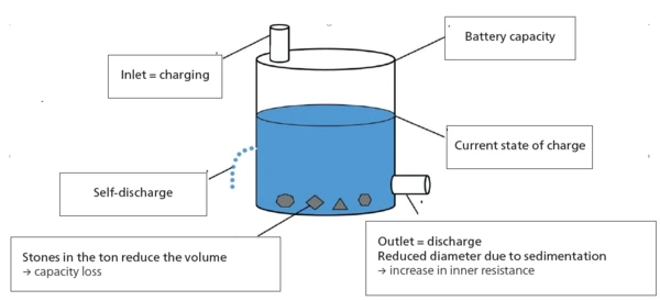
Describing the current state of an energy storage system well can be more difficult than it first appears. According to [7], the barrel model serves to illustrate well, as it does a good job of visually describing the most important influential factors during use and, in particular, those due to aging processes (fig. 3). The model compares the energy storage system with a rain barrel, where the level of the liquid in the barrel represents the current state of charge. The total volume in the new state corresponds to the maximum capacity of 100%. At the bottom of the barrel is an outlet for “discharging” and at the top an inlet for “charging”. The limited diameters of the inlet and outlet illustrate that there is a limit to the speed at which the barrels can be charged or discharged. This limitation corresponds to the internal resistance in the accumulator. Even when the inlet and outlet are closed, the barrel loses fluid over time because it has small holes and is therefore not perfectly tight. These losses represent the self-discharge of an accumulator. Aging of the accumulator is further described by the formation of “stones”. They reduce the usable volume of the barrel and thus the capacity of the energy storage system. Also, the barrel rusts over time, increasing the number of small holes and thus the losses due to “self-discharge”.
With this model, shown in figure 3, the most important processes in the operation of an accumulator can be described. The current state of an energy storage system is also referred to as the “state-of-health”.
Losses During Charging and Discharging
Regardless of the battery status, energetic losses also occur during each charging and discharging process. We all know from our own experience that cell phones or laptops heat up during intensive operation and also during charging. These heat developments represent energetic losses, because the quantities of heat released in this way are not available for actual use through the energy storage system.
With the help of the sensor in the Coin Cell Module of the MMC (figure 2), these heat losses can be detected and quantified.
Control of Charging and Discharging Cycles
Lithium-ion batteries are very sensitive with regard to overcharging, as this can easily lead to Reação de DecomposiçãoA decomposition reaction is a thermally induced reaction of a chemical compound forming solid and/or gaseous products. decomposition of the electrolytes. Therefore, common charging methods usually limit the maximum charging voltage to 4.2 V [7]. Also in this work, the charging and discharging cycles of a lithium-ion cell (LiR 2032) were limited using a cutoff voltage of 4.2 V for charging and 2.5 V for discharging. This results in the cycle shown as an example in figure 4. After a precharge cycle (not shown here), the coin cell is charged at 25°C with a constant current of 45 mA up to a cutoff voltage of 4.2 V 1 . In the subsequent RelaxationWhen a constant strain is applied to a rubber compound, the force necessary to maintain that strain is not constant but decreases with time; this behavior is known as stress relaxation. The process responsible for stress relaxation can be physical or chemical, and under normal conditions, both will occur at the same time. relaxation phase 2 , the coin cell and the sensor return to thermal equilibrium. The dicharging phase 3 is limited by the cutoff voltage of 2.5 V and is again followed by a RelaxationWhen a constant strain is applied to a rubber compound, the force necessary to maintain that strain is not constant but decreases with time; this behavior is known as stress relaxation. The process responsible for stress relaxation can be physical or chemical, and under normal conditions, both will occur at the same time. relaxation phase 4.
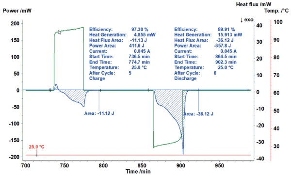
The current and voltage signals are transferred from the cycling unit to the NETZSCH Proteus® evaluation software where a power signal is automatically calculated. For determination of the losses during charging and discharging, the invested power and the heat released can thus be determined independently for each partial cycle. This way, it is possible to indicate what proportion of invested energy was released as heat.
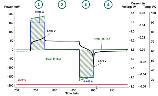
Figure 5 shows how the area evaluation of the heat-flux signal of the charging process automatically calculates the energy invested (here 411.6 J) and puts it into proportion with the heat-flux signal measured (here 11.12 J). This results in an efficiency of 97.3%. For the subsequent discharging, the efficiency amounts to only 89.9% due to the significantly higher heat generation.
Different Charging and Discharging Rates
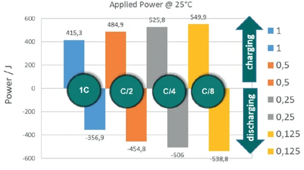
If charging and discharging cycles are carried out at different rates according to the aforementioned shutoff criteria, it can be seen that the energy absorbed by the energy storage system, and thus, of course, the amount of energy available during discharging, depends very strongly on the respective rate (figure 6). If the identical cell (LiR 2032) is charged at 45 mA (C/1), 415 J are absorbed, whereas at a charging rate of C/8 (5.6 mA), almost 550 J are absorbed.
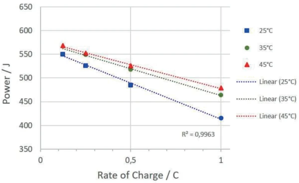
The temperature at which the accumulator is cycled also has an influence on the amount of energy absorbed and the charging and discharging efficiency. Figure 7 depicts the absorbed energies of the charging cycles at different temperatures.
Summary
The MMC Coin Cell Module 274 Nexus® was used to investigate a rechargeable LiR 2032 coin cell at different temperatures and different charging rates with regard to the heat thereby occurring. For the charging cycles, an upper and lower cutoff voltage of 4.2 V and 2.5 V were used. The power delivered to the accumulator by the cycling unit during charging can be quantified from the current and voltage signals of the cycling unit. The heat released during this process is directly measured by the sensor of the Coin Cell Module. The ratio of the power transferred to the accumulator and the amount of heat released allows the efficiency for the charging and discharging processes to be determined independently. It has been shown that both the power absorbed and the respective charging and discharging efficiency are strongly dependent on the charging rates and temperature.