Determinação da condição da bateria
Quando se trata de usar uma unidade de armazenamento de energia, seu "nível de carga" atual é sempre interessante, seja para avaliar o tempo de funcionamento restante de um telefone celular ou laptop, seja em relação à autonomia de um veículo elétrico. Embora o tempo de carregamento possa ter um papel secundário para um celular ou laptop, ele pode ser de particular importância no contexto da eletromobilidade.
Descrever bem o estado atual de uma unidade de armazenamento de energia pode ser mais difícil do que parece à primeira vista. Uma boa ilustração do estado atual de um acumulador é o modelo de barril [1]. Esse modelo já foi descrito em detalhes em relação ao ciclo de células de moeda [2]. A seguir, será investigado o desenvolvimento de calor durante a carga e a descarga de células 18650, ou seja, baterias significativamente larger do que células tipo moeda.
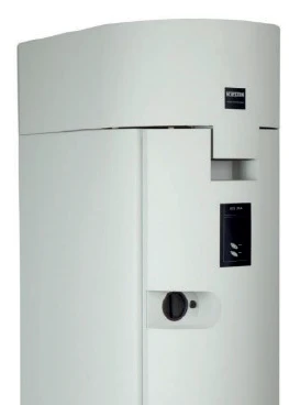
O site NETZSCH ARC® 254
O NETZSCH Calorimetria de taxa acelerada (ARC)O método que descreve os procedimentos de teste isotérmico e adiabático usados para detectar reações de decomposição termicamente exotérmicas.ARC® 254 (figura 1) é um Calorímetro de Taxa de Aceleração, um instrumento normalmente usado para investigar a chamada Fuga térmicaO descontrole térmico é a situação em que um reator químico fica fora de controle em relação à produção de temperatura e/ou pressão causada pela própria reação química. A simulação de um descontrole térmico geralmente é realizada usando um dispositivo de calorímetro de acordo com a calorimetria de taxa acelerada (ARC).fuga térmica de substâncias individuais ou misturas de reações [3]. Com relação ao ciclo de baterias, entretanto, o Calorimetria de taxa acelerada (ARC)O método que descreve os procedimentos de teste isotérmico e adiabático usados para detectar reações de decomposição termicamente exotérmicas.ARC® 254 deve ser usado como um calorímetro IsotérmicoOs testes com temperatura controlada e constante são chamados de isotérmicos.isotérmico. Para esse fim, a configuração do Calorimetria de taxa acelerada (ARC)O método que descreve os procedimentos de teste isotérmico e adiabático usados para detectar reações de decomposição termicamente exotérmicas.ARC® 254 pode ser usada de maneira especial. Para as investigações de segurança mencionadas acima, a câmara do calorímetro real no Calorimetria de taxa acelerada (ARC)O método que descreve os procedimentos de teste isotérmico e adiabático usados para detectar reações de decomposição termicamente exotérmicas.ARC® 254 é cercada por vários aquecedores independentes. Para o exame IsotérmicoOs testes com temperatura controlada e constante são chamados de isotérmicos.isotérmico de acumuladores, eles são cercados por outro aquecedor no calorímetro, de modo que a temperatura da bateria possa ser controlada independentemente do calorímetro.
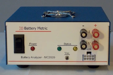
células 18650
As chamadas células 18650 são células padrão do setor em um invólucro cilíndrico de metal com diâmetro de 18 mm e altura de 65,0 mm (figura 2).
A bateria é colocada em um aquecedor que envolve a célula cilíndrica (figura 3) e instalada na câmara de medição do calorímetro.
A bateria é conectada à unidade de ciclagem externa (figura 4) por meio de um plugue conector simples, a fim de aplicar corrente e EstirpeA deformação descreve uma deformação de um material, que é carregado mecanicamente por uma força ou estresse externo. Os compostos de borracha apresentam propriedades de deformação se uma carga estática for aplicada.tensão para carga e descarga.
O interesse em determinar os balanços térmicos das baterias durante a carga e a descarga, embora seja um dos principais problemas atuais, não é totalmente novo. Embora a configuração no NETZSCH ARC® 254 descrita abaixo seja diferente dos modelos da literatura, a abordagem básica é idêntica à descrita por Hansen et al. em 1982 [4].


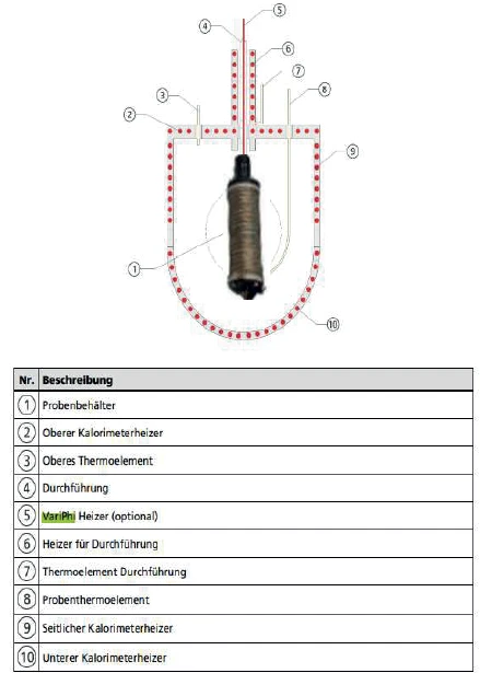
O aquecedor 3D-VariPhi
Como já foi indicado, a bateria cilíndrica é cercada diretamente pelo aquecedor 3D-VariPhi ( 5 na fig. 5). Ele precisa fornecer uma certa quantidade de calor para manter a bateria em uma temperatura constante e, portanto, requer uma certa quantidade de energia. A energia necessária depende de vários fatores, entre os quais a temperatura ambiente.
Para criar um sistema de controle suficientemente longo, os outros aquecedores do calorímetro (2, 6, 9 e 10 na figura 5) são ajustados para uma temperatura mais baixa constante. Se os processos energéticos durante a carga e a descarga da bateria alterarem a temperatura da célula, a fonte de alimentação do aquecedor 3D-VariPhi (5) poderá reagir imediatamente e, assim, garantir uma temperatura constante na bateria. A partir da saída registrada do aquecedor 3D-VariPhi ( 5 ), por sua vez, é possível determinar diretamente o calor absorvido ou liberado pela bateria durante os ciclos.
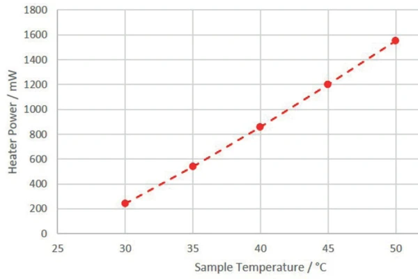
Como a potência exigida pelo aquecedor 3D-VariPhi para manter a temperatura da bateria é importante, a relação entre a potência de aquecimento e a temperatura da bateria é registrada na figura 6.
Ciclo de uma célula 18650
A célula 18650 a ser investigada foi mantida a uma temperatura constante de 35°C pelo aquecedor 3D-VariPhi. Após um processo de carregamento definido (corte de 2,5 V), essa bateria de íons de lítio foi carregada (4,2 V, limite l de 100 mA) usando o chamado processo de carregamento CC/CV (corrente constante/EstirpeA deformação descreve uma deformação de um material, que é carregado mecanicamente por uma força ou estresse externo. Os compostos de borracha apresentam propriedades de deformação se uma carga estática for aplicada.tensão constante). Depois de um intervalo de 120 minutos, seguiu-se a descarga. Esses dois processos foram repetidos uma vez. As correntes de carga e descarga usadas estão resumidas na tabela 1.
Tabela 1: Correntes de carga e descarga
| Carga | Descarga | |
| 1C | 1500 mA | 1500 mA |
| C/2 | 750 mA | 750 mA |
| C/4 | 375 mA | 375 mA |
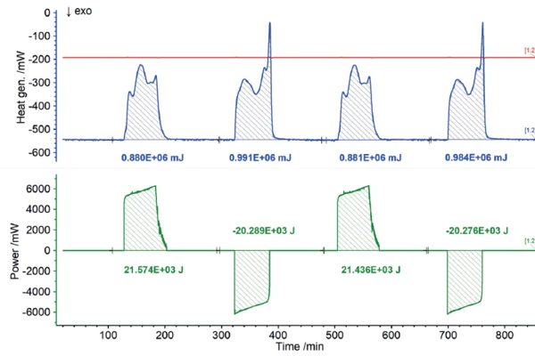
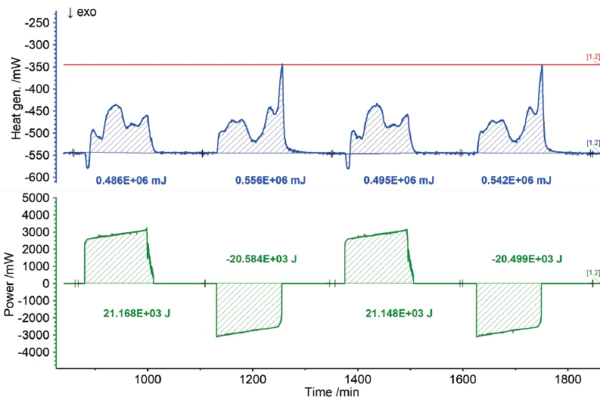
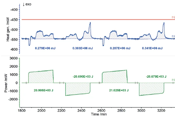
Todos os usuários sabem, por experiência própria, que os telefones celulares ou laptops esquentam durante a operação intensiva e, da mesma forma, durante o carregamento. Em termos do ciclo de carga, esses desenvolvimentos de calor representam perdas de energia, pois a parte do calor liberada dessa forma não está disponível para uso real pela unidade de armazenamento de energia. Consequentemente, as quantidades de calor detectadas pelo ARC® 254 durante a carga e a descarga podem ser registradas como perdas em termos de eficiência de carga. Os resultados do calor de reação da célula 18650 em função de diferentes taxas de carga são mostrados nas figuras 7 a 9. Se a potência de carga ou descarga investida for comparada com os calores de reação medidos, ou seja, as perdas, a eficiência dos ciclos parciais poderá ser determinada de forma independente.
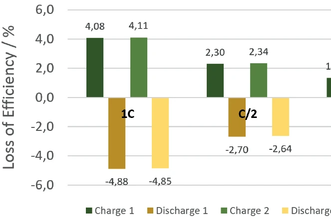
Resumo
O NETZSCH ARC® 254 foi usado para fazer o ciclo de uma bateria cilíndrica (18650) a 35°C em diferentes taxas de carga (1C, C/2, C/4). Os calores de reação detectados correspondem às perdas térmicas, o que permite que a eficiência dos ciclos de carga e descarga seja determinada independentemente um do outro. Se não houvesse perdas, a eficiência seria de 100%. As perdas determinadas a partir dos calores de reação são resumidas para os ciclos de carga e descarga, mas também para as diferentes taxas de carga, na Figura 10. Fica claro que, para taxas de carga baixas (C/4), as perdas são menores e, portanto, a eficiência é maior do que para taxas de carga mais altas (1C).