Introduction
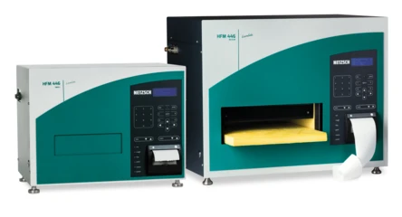
Known insulation materials like mineral wool or polymer foams are usually produced with high thickness (several centimeters) to meet the required U-value for the thermal insulation of buildings. A suitable measurement device for determination of the Thermal ConductivityThermal conductivity (λ with the unit W/(m•K)) describes the transport of energy – in the form of heat – through a body of mass as the result of a temperature gradient (see fig. 1). According to the second law of thermodynamics, heat always flows in the direction of the lower temperature.thermal conductivity (λ) is the HFM 446 LambdaMedium (figure 1). However, insulation materials are also applied in other areas with other thicknesses, for example, in the thermal and sound insulation of floors. The thickness of such insulation materials is often only a few millimeters. The following measurements show how such thin materials can successfully be investigated with the HFM 446 LambdaMedium.
U-Value
The U-value reflects the heat flow through a component dependent on the temperature gradient between the wam and cold side of a unit [W/(m2·K)]. The unit describes the energy flowing through 1 square meter due to a temperature difference of 1 K. This value characterizes the insulation properties of a component; this means in practice, the lower the U-value, the better the insulating effect. The higher the U-value, the poorer the insulating effect. The building then loses more heat on cold winter days.
Measurement Method
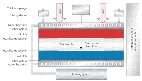
A temperature gradient is defined between two plates by a material to be measured. By means of two highprecision heat-flow sensors in the plates, the heat flow into the material and out of the material, respectively, is measured. Once equilibrium of the system is reached and the heat flow is constant, the Thermal ConductivityThermal conductivity (λ with the unit W/(m•K)) describes the transport of energy – in the form of heat – through a body of mass as the result of a temperature gradient (see fig. 1). According to the second law of thermodynamics, heat always flows in the direction of the lower temperature.thermal conductivity can be calculated with the help of the Fourier equation and knowledge of the measurement area and thickness of the sample (see schematic figure 2).
λ Thermal conductivity [W/(m∙K)]
d Thickness [mm]
R = d/ λ Thermal resistance [m2∙K/W]
U = 1/R Heat transfer coefficient [W/(m2∙K)]
Measurement Conditions
A natural fiber insulation board with a thickness of 4 mm was investigated. The thermal resistance (R = d/λ) of such thin samples presents a challenge for measurement. Samples with thermal resistance lower than approximately 0.5 m²∙K/W cannot be measured with the HFM as a standard measurement (DIN EN 12667). The Contact ResistanceAccording to the second law of thermodynamics, heat transfer between two systems always moves in the direction from higher to lower temperatures. The amount of thermal energy transferred by heat conduction, e.g., through a wall of a building, is influenced by the thermal resistances of the concrete wall and the insulation layer.contact resistance between the plates and sample is no longer negligible and will affect the result. To overcome the issue of low thermal resistance, measurements with two different approaches were performed:
- Stacking of samples, mentioned in DIN EN 12667
- Measurement of one sample with additional external thermocouple and interface layers (=instrumentation kit), described in DIN EN 12664 for samples with a thermal resistance of < 0.5 m2∙K/W.
The measurements were carried out at a mean sample temperature of 25°C. The temperature difference between the plates was 20 K. The pressure on the sample was approximately 2 kPa.
Stacking of Samples
Figure 3 shows the Thermal ConductivityThermal conductivity (λ with the unit W/(m•K)) describes the transport of energy – in the form of heat – through a body of mass as the result of a temperature gradient (see fig. 1). According to the second law of thermodynamics, heat always flows in the direction of the lower temperature.thermal conductivity versus the overall thickness of stacked samples (1 to 8 layers). The measurement data is summarized in table 1.
In the low thickness range, the Thermal ConductivityThermal conductivity (λ with the unit W/(m•K)) describes the transport of energy – in the form of heat – through a body of mass as the result of a temperature gradient (see fig. 1). According to the second law of thermodynamics, heat always flows in the direction of the lower temperature.thermal conductivity shows a dependence on thickness. The Contact ResistanceAccording to the second law of thermodynamics, heat transfer between two systems always moves in the direction from higher to lower temperatures. The amount of thermal energy transferred by heat conduction, e.g., through a wall of a building, is influenced by the thermal resistances of the concrete wall and the insulation layer.contact resistance between the sample and HFM plates affects the result (reduced Thermal ConductivityThermal conductivity (λ with the unit W/(m•K)) describes the transport of energy – in the form of heat – through a body of mass as the result of a temperature gradient (see fig. 1). According to the second law of thermodynamics, heat always flows in the direction of the lower temperature.thermal conductivity).
With a thickness higher than 20 to 24 mm (5 to 6 layers), the Thermal ConductivityThermal conductivity (λ with the unit W/(m•K)) describes the transport of energy – in the form of heat – through a body of mass as the result of a temperature gradient (see fig. 1). According to the second law of thermodynamics, heat always flows in the direction of the lower temperature.thermal conductivity is constant and no longer dependent on thickness. This is the region where the Contact ResistanceAccording to the second law of thermodynamics, heat transfer between two systems always moves in the direction from higher to lower temperatures. The amount of thermal energy transferred by heat conduction, e.g., through a wall of a building, is influenced by the thermal resistances of the concrete wall and the insulation layer.contact resistance is negligible and measurements can be considered reliable. The thermal resistance of the sample is higher than approximately 0.5 (m²∙K)/W.
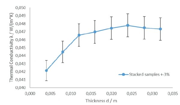
Table 1: Measurement results of the stacked samples of a 4-mm thick naterual insulation fiber board
Number of Layers | Thickness [mm] | [W/(m∙K)] | [(m2∙K)/W] |
|---|---|---|---|
| 1 | 4 | 0.04214 | 0.0958 |
| 2 | 8 | 0.04447 | 0.1812 |
| 3 | 12 | 0.04565 | 0.2582 |
| 4 | 16 | 0.04697 | 0.3387 |
| 5 | 20 | 0.04745 | 0.4214 |
| 6 | 24 | 0.04779 | 0.5021 |
| 7 | 28 | 0.04749 | 0.5906 |
| 8 | 32 | 0.04734 | 0.6757 |
* all results ± 3%
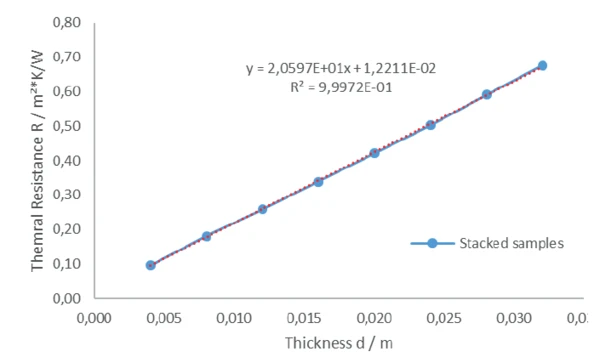
Figure 4 (thermal resistance over thickness) confirms that the measurements with stacked samples are reliable. The thermal resistance increases linearly with increasing thickness. The linear trend line gives an R² fit of 0.99972 and the slope is an indicator for the Thermal ConductivityThermal conductivity (λ with the unit W/(m•K)) describes the transport of energy – in the form of heat – through a body of mass as the result of a temperature gradient (see fig. 1). According to the second law of thermodynamics, heat always flows in the direction of the lower temperature.thermal conductivity (slope m = R/d = 1/λ → λ = 0.04855 W/(m∙K)). This value is in good agreement with the measurement results of the stacked sample with a thickness higher than ~20 mm; see table 1.
Instrumentation Kit
For low thermal resistance samples, measurements with the instrumentation kit (= external thermocouples and interface layers) can also be a good solution. The issue of Contact ResistanceAccording to the second law of thermodynamics, heat transfer between two systems always moves in the direction from higher to lower temperatures. The amount of thermal energy transferred by heat conduction, e.g., through a wall of a building, is influenced by the thermal resistances of the concrete wall and the insulation layer.contact resistance is solved by direct measurement of the surface temperature. For stiff samples, the instrumentation kit is a good choice. Since the 4-mm thick natural fiber insulation board ist not completely stiff but still flexible, another source of uncertainty exists. The external thermocouples can penetrate into the sample’s surfaces.
Therefore, the thickness (= distance between the external thermocouples) is not precisely known. Due to the low thickness of only 4 mm, even a low level of penetration can cause a high deviation in the result (relative error in thickness causes the same relative error in Thermal ConductivityThermal conductivity (λ with the unit W/(m•K)) describes the transport of energy – in the form of heat – through a body of mass as the result of a temperature gradient (see fig. 1). According to the second law of thermodynamics, heat always flows in the direction of the lower temperature.thermal conductivity).
Table 2 shows the results of a measurement with the instrumentation kit. The measurement of one layer with the instrumentation kit produces a value that is approximately 10% higher than the results from the stacked samples. This 10% increase in the Thermal ConductivityThermal conductivity (λ with the unit W/(m•K)) describes the transport of energy – in the form of heat – through a body of mass as the result of a temperature gradient (see fig. 1). According to the second law of thermodynamics, heat always flows in the direction of the lower temperature.thermal conductivity value is most probably caused by a thickness value that is incorrect by 10% due to enetration by the external thermocouple (200 μm on each side). This is confirmed by the measurement of 1 and 2 layers with the instrumentation kit and calculation of the Thermal ConductivityThermal conductivity (λ with the unit W/(m•K)) describes the transport of energy – in the form of heat – through a body of mass as the result of a temperature gradient (see fig. 1). According to the second law of thermodynamics, heat always flows in the direction of the lower temperature.thermal conductivity with adjusted thickness (= thickness minus 2 x 200 μm). The thermal conductivity with adjusted thickness is in good agreement with the values from the measurements with stacked samples.
Table 2: Measurement results of the 4-mm thick natural fiber insulation board with instrumentation kit
Number of Layers | Thickness [mm] | [W/(m·K)] | Adjusted Thickness [mm] | Adjusted Thickness [W/(m∙K)] |
|---|---|---|---|---|
| 1 | 4 | 0.05281 | 3.6 | 0.04753 |
| 2 | 8 | 0.05071 | 7.6 | 0.04817 |
Summary
The thermal conductivity of thin and flexible insulation materials can be measured with the HFM 446 LambdaMedium by stacking several layers of the material to a sufficient thickness. Measurement with external thermocouples instrumentation kit) on flexible samples can result in falsely inflated thermal conductivity values due to the possible penetration of the thermocouples into the sample’s surface.