Introduction
Along with a fast data acquisition and capable software, it is also necessary to have a flash system with an efficient energy source to reach an optimal energy input within a short time. The smaller the pulse width, the faster can the temperature increase be. This means, the minimum possible sample thickness also depends on the minimum possible pulse width. Only flash systems with high sensitivity and sufficient pulse energy at a minimum pulse width can measure thin and fast samples with high accuracy.
Test Conditions
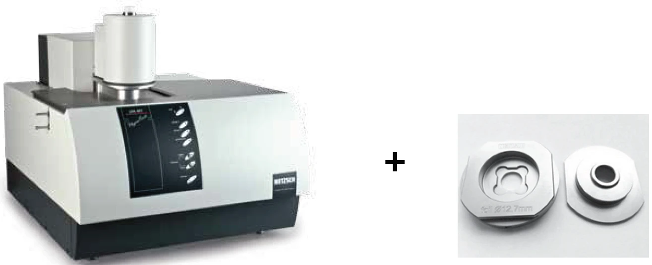
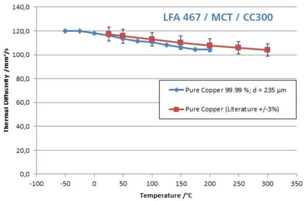
Figure 2 depicts the measurement results on a thin copper sample with a thickness of only 235 μm. The LFA 467 HyperFlash® (figure 1) with CC300 cooling system and the highly sensitive MCT detector were used. The MCT detector ensures the best signal-to-noise-ratio in the low-temperature range and features the advantage of a contactless measurement (no measurement error due to thermal Contact ResistanceAccording to the second law of thermodynamics, heat transfer between two systems always moves in the direction from higher to lower temperatures. The amount of thermal energy transferred by heat conduction, e.g., through a wall of a building, is influenced by the thermal resistances of the concrete wall and the insulation layer.contact resistance between the sensor and sample). The small time constant and the excellence response characteristics of the MCT detector compared to, e.g., a solid-state detector allow for the detection of diffusion times of less than 1 ms with high accuracy. This requires also smallest pulse lengths which can be reduced to 10 μs and a high data acquisition speed of 2 MHz (two separate 2-MHz channels for the IR detector and pulse diode).
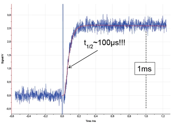
Thanks to the high sensitivity of the system electronics, it is possible to get a reliable detector signal also at a minimum pulse width of 10 μs. This can be seen in figure 3. In the past, commercial flash systems were working with pulse lengths of 150 μs to 1200 μs and more. A half-time of 100 μs, as can be seen in figure 3, could not be detected so far. The detector curve (blue) and the corresponding model fit (red curve) are in good agreement. The patented finite pulse correction and an improved 2-D calculation model on the basis of Cape-Lehman were used for calculation of the Thermal DiffusivityThermal diffusivity (a with the unit mm2/s) is a material-specific property for characterizing unsteady heat conduction. This value describes how quickly a material reacts to a change in temperature.thermal diffusivity. In figure 2, it can clearly be seen that the maximum deviation from literature values is less than 3%.
Conclusion
Special attention must be given to the very short duration of 1 ms which was not possible with commercial flash systems in the past. A signal increase within ~200 μs (heat diffusion time) can now be detected thanks to the very short pulse width of 10 μs and the high data acquisition speed of 2 MHz.