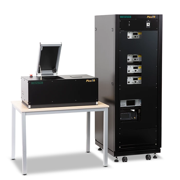
PicoTR
Time Domain ThermoreflectanceThermoreflectance ist eine Methode zur Bestimmung der Temperaturleitfähigkeit und Wärmeleitfähigkeit von Proben mit Dicken im Nano- und Mikrometer-Bereich.Thermoreflectance mittels Pulsed Light Heating
Highlights
The Method for the Determination of Thermal Diffusivity in the Thickness Range of Nanometer
Time Domain Thermoreflectance Methods
The Method for the Determination of Thermal Diffusivity in the Thickness Range of Nanometer
With the significant progress in the design of electronic devices and the associated need for an efficient thermal management, accurate thermal diffusivity / thermal conductivity measurements in the nanometer range are more than ever crucial.
The National Institute of Advanced Industrial Science and Technology (AIST), Japan, already responded to industrial requirements with the development of a “pulsed light heating ThermoreflectanceThermoreflectance ist eine Methode zur Bestimmung der Temperaturleitfähigkeit und Wärmeleitfähigkeit von Proben mit Dicken im Nano- und Mikrometer-Bereich.thermoreflectance method” in the early 90’s. PicoTherm Corporation was established in 2008 with the launch of a nano-second thermoreflectance apparatus “NanoTR” and a pico-second thermoreflectance apparatus “PicoTR”, which allows for absolute measurements of the thermal diffusivity of thin films in a thickness range of several 10 μm down into the nanometer range.
In October 2020, PicoTherm joined the NETZSCH Group as a subsidiary of NETZSCH Japan. In combination with our LFA systems, NETZSCH can now offer the solution for thin films in the nanometer range up to bulk materials in the range of mm.
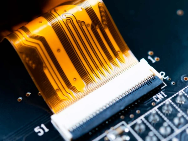
With the significant progress in the design of electronic devices and the associated need for an efficient thermal management, accurate thermal diffusivity / thermal conductivity measurements in the nanometer range are more than ever crucial.
The National Institute of Advanced Industrial Science and Technology (AIST), Japan, already responded to industrial requirements with the development of a “pulsed light heating thermoreflectance method” in the early 90’s. PicoTherm Corporation was established in 2008 with the launch of a nano-second thermoreflectance apparatus “NanoTR” and a pico-second thermoreflectance apparatus “PicoTR”, which allows for absolute measurements of the thermal diffusivity of thin films in a thickness range of several 10 μm down into the nanometer range.
Methode
Time Domain Thermoreflectance Methods – The Laser Flash Methode for thin films
Mit der PicoTR lassen sich Laserpulse (Pump-Laser) mit einer Pulsbreite von 0,5 ps mit einer Zeitperiode von 50 ns auf die Probe aufbringen. Die Temperaturansprechzeit wird ebenfalls mittels Probe-Laser detektiert.
PicoTR erlaubt dem Anwender ein einfaches Umschalten zwischen RT- und FF-Modus.
PicoTR stimmt mit den japanischen Industriestandards JIS R 1689 und JIS R 1690 überein.
Thermoreflectance Methods
Ultrafast Laser Flash Method – Rear Heating/Front Detection (RF)
Determination of Thermal Diffusivity and Interfacial Thermal Resistance
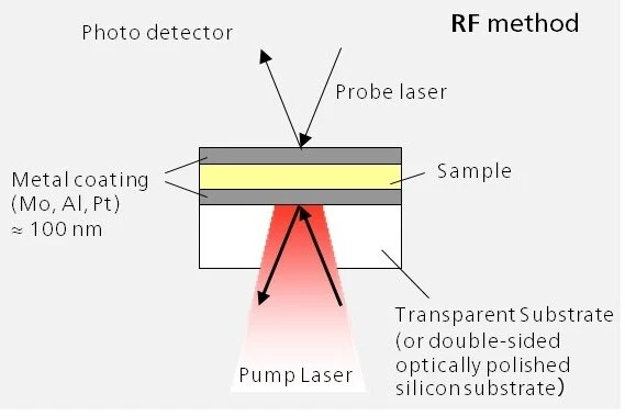
The fact that the thermophysical properties of thin layers and films differ considerably from those of the corresponding bulk material requires a technique which overcomes the limitations of the classical laser flash method (LFA). This so-called ultrafast laser flash technique is also known as the rear heating/front detection method.
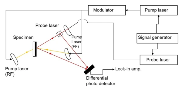
The measurement setup is similar to the conventional LFA: detector and laser are on opposite sides of the sample which is located on a transparent substrate. The measured thermal diffusivity is the component through the thickness perpendicular to the sample’s surface. The pump laser irradiates the sample’s rear side.
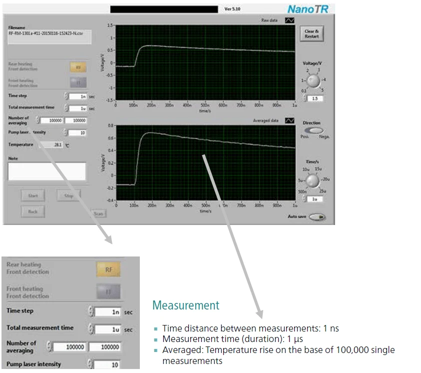
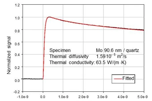
As the sample heats up, its surface thermoreflectance varies. The thermal diffusivity is calculated from the temperature rise (lower plot). Here, the thermal diffusivity of a thin metal film (Mo) was determined to 1.59 • 10-5 m2/s.
Time Domain Thermoreflectance - Front Heating/Front Detection (FF)
Determination of Thermal Diffusivity and Thermal Effusivity
In addition to the RF method, measurements can also be made in a front heating/front detection (FF) configuration. The term “front” refers to the open surface of the thin film deposited on a substrate, while “rear” refers to the boundary between the thin film and the substrate.
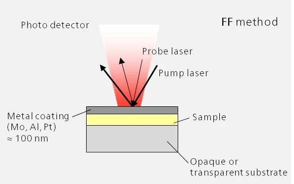
In the FF measurement setup (upper picture), the detector and laser are on the same side of the sample. An area of the front face of the thin film with a diameter of several tens of micrometers is heated by a pump laser, and a probe laser points at the same position. The change in the surface temperature is observed.
This method can be applied to thin layers on non-transparent substrates for which the RF technique is not suitable.
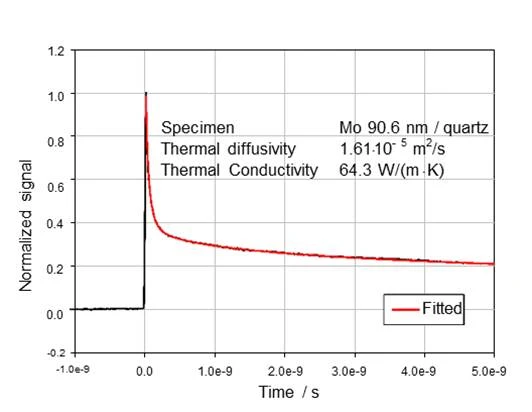
In the example on the left, the thermal diffusivity of a thin metal film (Mo) was determined to 1.61 • 10-5 m2/s by applying the FF method. The results prove the high agreement between RF and FF modes (deviation < 2%).
Thermoreflectance Methoden
Bestimmung von TemperaturleitfähigkeitDie Temperaturleitfähigkeit (a mit der Einheit mm2/s) ist eine materialabhängige Stoffeigenschaft zur Charakterisierung des instationären Wärmetransports. Sie gibt an, wie schnell ein Material auf eine Temperaturänderung reagiert.Temperaturleitfähigkeit und Wärmeeindringkoeffizient
Zusätzlich zur RF-Methode sind auch Messungen in der Konfiguration „Aufheizung Vorderseite/Detektion Vorderseite (engl. front heating/front detection, FF) möglich. Der Begriff „Vorderseite“ bezieht sich auf die offene Oberfläche der auf dem Substrat aufgebrachten dünnen Schicht, während sich der Begriff „Rückseite“ auf die Grenze zwischen der dünnen Schicht und dem Substrat bezieht.
Im FF-Messaufbau (untere Abbildung) befinden sich Detektor und Laser auf der gleichen Seite der Probe. Ein Bereich der Vorderseite der dünnen Schicht mit einem Durchmesser von einigen zehn Mikrometern wird durch einen Pumplaser aufgeheizt, wobei der Probe-Laser in dieselbe Richtung zeigt. Die Änderung der Oberflächentemperatur wird aufgezeichnet.
Diese Methode kann auf dünne Schichten auf nicht transparenten Substraten angewandt werden, für die die RF-Methode nicht geeignet ist.
Im Beispiel auf der linken Seite wurde die Temperaturleitfähigkeit einer dünnen Metall-schichten (Mo) zu 1,61 • 10-5 m2/s mittels-FF-Methode bestimmt. Die Ergebnisse bestätigen die hohe Übereinstimmung zwischen dem RF- und FF-Modus (Abweichung < 2 %).
Time Domain Thermoreflectance - Aufheizung Vorderseite/Detektion Vorderseite (FF)
Bestimmung von Temperaturleitfähigkeit und des Wärmewiderstands von Zwischenschichten
Die Tatsache, dass die thermophysikalischen Eigenschaften von dünnen Schichten und Folien von denen der Bulkmaterialien beträchtlich abweichen, erfordert eine Technik, die die Einschränkungen der klassischen Laser Flash-Methode (LFA) in Bezug auf die minimale Probendicke überwindet. Diese sogenannte ultraschnelle Laser Flash-Technik ist auch als Methode „Aufheizung Rückseite/Detektion Vorderseite“ (engl. rear heating/front detection, RF) bekannt.
Der Messaufbau ist ähnlich zur konventionellen LFA: Detektor und Laser befinden sich auf den gegenüberliegenden Seiten der auf einem Substrat angebrachten Probe. Die gemessene Temperaturleitfähigkeit ist die Komponente durch die Dicke senkrecht zur Probenoberfläche. Der Pumplaser bestrahlt die Probenrückseite.
Mit Aufheizung der Probe variiert deren Oberflächenreflektivität. Die Temperaturleitfähigkeit errechnet sich aus dem Temperaturanstieg (unterer Plot). In diesem Beispiel wurde die Temperaturleitfähigkeit einer dünnen Metallschicht (Mo) mit 1.59 • 10-5 m2/s bestimmt.
Ultraschnelle Laser Flash-Methode - Aufheizung Rückseite/Detektion Vorderseite (RF)
Sowohl das NanoTR- als auch das PicoTR-Gerät erlauben die absolute Messung der Temperaturleitfähigkeit an lichtundurchlässigen Proben und transparentem Substrat. Für alle anderen Fälle wie lichtundurchlässiges Substrat und transparenter dünner Schicht sind Referenzmaterialien aus Molybdän (CRM 5808-a, für PicoTR) und TiN (RM 1301-a, für NanoTR) durch AIST erhältlich. Die NanoTR und PicoTR sind kalibriert, um die Rückführbarkeit auf japanische Standards zu sichern. Die Apparaturen sind in Übereinstimmung mit den japanischen Industriestandards (JIS):
- JIS R 1689 “Determination of thermal diffusivity of fine ceramic films by pulsed light heating thermoreflectance method”
- JIS R 1690 “Determination of interfacial thermal resistance between fine ceramic film and metal film”
“Light Pulse Heating Thermoreflectance Methods for Thermophysical Property Measurements of Thin Films”
Tetsuya BABA
“Development of thin film reference material for thermal diffusivity”
Takashi YAGI, Naoyuki TAKETOSHI, Tetsuya BABA
“Direct observation of thermal energy transfer across the thin metal film on silicon substrates by a rear heating front detection thermoreflectance technique ”
Shakhawat H. FIROZ, Takashi YAGI, Naoyuki TAKETOSHI, Kazuko ISHIKAWA, Tetsuya BABA
“Thermal diffusivity measurement in a diamond anvil cell using a light pulse thermoreflectance technique”
Takashi YAGI, Tetsuya BABA, et al.
Specifications
| PicoTR | ||
|---|---|---|
| Pump Laser | Pulsbreite Wellenlänge Strahlendurchmesser | 0.5 ps 1550 nm 45 μm |
| Probe Laser | Pulsbreite Wellenlänge Strahlendurchmesser | 0.5 ps 775 nm 25 μm |
| Messwerte | Temperaturleitfähigkeit und Wärmeeindringkoeffizienten, Wärmewiderstand von Zwischenschichten | |
| Probenschichtdicke (RF-Methode) | Harz Keramik Metall | 10 nm ... 100 nm 10 nm ... 300 nm 100 nm ... 900 nm |
| Probenschichtdicke (FF-Methode) | Dicker als 100 nm | |
| Substrate | Material Größe Dicke | Lichtundurchlässig/transparent 10 ... 20 mm quadratisch 1 mm max. |
| Temperaturleitfähigkeit | Reichweite | 0.01 ... 1000 mm²/s |
| Genauigkeit | ± 6,2 % mit einer Messzeit von 40 min, für CRM 5808A im RF-Modus, 400 nm Dicke | |
| Reproduzierbarkeit | ± 5% | |
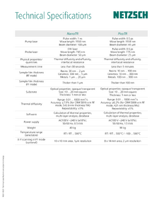
| Software | Berechnung der thermischen Eigenschaften, Mehrschichtanalyse, Datenbank |
| PicoTR | ||
|---|---|---|
| Pump Laser | Pulse width Wavelength Beam diameter | 0.5 ps 1550 nm 45 μm |
| Sample Laser | Pulse width Wavelength Beam diameter | 0.5 ps 775 nm 25 μm |
| Measured values | Thermal diffusivity and heat penetration coefficients, thermal resistance of intermediate layers | |
| Sample layer thickness (RF method) | Resin Ceramic Metal | 10 nm ... 100 nm 10 nm ... 300 nm 100 nm ... 900 nm |
| Sample layer thickness (FF method) | Thicker than 100 nm | |
| Substrates | Material Size Thickness | Opaque/transparent 10 ... 20 mm square 1 mm max. |
| Thermal diffusivity | Range | 0.01 ... 1000 mm²/s |
| Accuracy | ± 6.2 % with a measuring time of 40 min, for CRM 5808A in RF mode, 400 nm thickness | |
| Reproducibility | ± 5% | |
| Software | Calculation of thermal properties, multilayer analysis, database |
Software
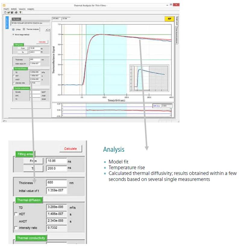
In-situ-Display und Analysieren von 100.000 Schüssen
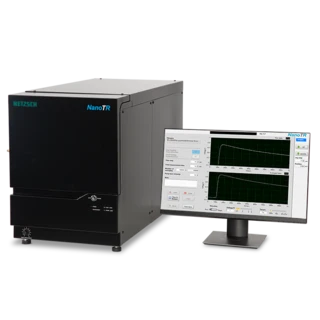
Die moderne Mess-/Analysesoftware von NanoTR/PicoTR bietet eine anwenderfreundliche Benutzeroberfläche, die die genaue Bestimmung der thermischen Eigenschaften von dünnen Schichten zulässt. Die Fokussierung des Laserstrahls wird über die Software mittels CCD-Kamera eingestellt.
Die NanoTR/PicoTR-Software läuft unter Microsoft Windows.
Der Plot zeigt, dass eine Messkurve in einer Messzeit von 1 μs erhalten werden kann.
Liefert Ergebnisse in nur wenigen Minuten