Introduction
In the chemical and process industries, it is often required to pump fluids over long distances from storage to various processing units and/or from one plant site to another. It is thus often necessary to calculate the pressure requirements for pumping, the selection of optimum pipe diameter as well as measurement and control of flow rate. Many of the formulae required to estimate such parameters are available in literature and require some knowledge of these processing parameters as well as fluid properties.
When dealing with Non-NewtonianA non-Newtonian fluid is one that exhibits a viscosity that varies as a function of the applied shear rate or shear stress.non-Newtonian fluids, it is often sufficient to consider them as power law fluids in terms of processing due to the shear rates involved.
If the liquid obeys power law behavior, then the pressure drop across the pipe can be described by the following equation (1):
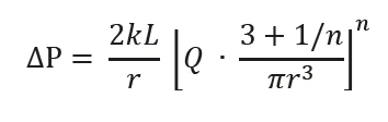
where k is the consistency and n the power law index; Q is the flow rate through the pipe radius r with a pressure drop ΔP. If the fluid is Newtonian then the power law index has a value of 1.
The shear rate encountered during this process is given by the following expression (2):

By measuring the volumetric flow rate for a given pipe diameter, it is therefore possible to estimate the shear rate encountered during the pumping process. If n is unknown at this stage, then it can be taken as 1, which is the value for a Newtonian fluid. Measuring the viscosity at selected shear rates slightly above and below the calculated value allows a relevant portion of the flow curve to be generated. A Power Law ModelThe power law model is a common rheological model to quantify (typically) the shear thinning nature of a sample, with the value closer to zero indicating a more shear thinning material.power law model can then be fitted to the data and values of k and n determined. These values can then be inputted in to equations 1 and 2 to yield the pressure drop across the pipe and the true shear rate respectively. These expressions assume steady state (fully developed) laminar flow and no slip conditions at the pipe walls.
Experimental
- This example considers a shampoo product being transported through a straight pipe with a radius of 0.0125 m and length of 10 m. The volumetric flow rate is 0.0005 m3/s and the power law index was known to be 0.15.
- Rotational rheometer measurements were made using a Kinexus rheometer with a Peltier plate cartridge and 40 mm roughened parallel plates measuring system (to avoid sample slip at the geometry surfaces)2, and utilizing standard pre-configured sequences in rSpace software.
- A standard loading sequence was used to ensure that samples were subject to consistent and controllable loading protocol. ∙ All rheology measurements were performed at 25°C.
- The relevant shear rate for flow in the pipe was automatically calculated as part of the test sequence using inputted values of pipe radius, length, volumetric flow rate and power law index
- A shear rate table using a start value of (calculated shear rate/2) and an end value of (calculated shear rate ×2) was performed, and a Power Law ModelThe power law model is a common rheological model to quantify (typically) the shear thinning nature of a sample, with the value closer to zero indicating a more shear thinning material.power law model fitted to the resultant flow curve and the calculated pressure drop determined.
Results and Discussion
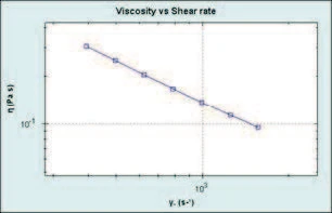
From the information provided, the calculated shear rate for flow in the pipe was determined to be 787 s-1. This automatically generated a table of shear rates between 394 s-1 and 1578 s-1 and produced a Shear ThinningThe most common type of non-Newtonian behavior is shear thinning or pseudoplastic flow, where the fluid viscosity decreases with increasing shear.shear thinning curve as shown in Figure 1.
A power law analysis on the resultant curve yielded values of k and n of 48.7 and 0.1506, respectively. These values where then used to determine the true shear rate (if n was not known initially), the pressure drop and the associated shear StressStress is defined as a level of force applied on a sample with a well-defined cross section. (Stress = force/area). Samples having a circular or rectangular cross section can be compressed or stretched. Elastic materials like rubber can be stretched up to 5 to 10 times their original length.stress.
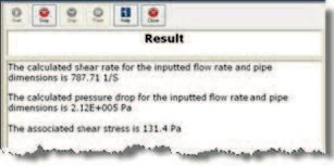
These calculated values were then displayed as a prompt in the rSpace software as shown in Figure 2.
To pump this material at the required flow rate will therefore require a pressure difference across the pipe of 212 kPa and an associated shear StressStress is defined as a level of force applied on a sample with a well-defined cross section. (Stress = force/area). Samples having a circular or rectangular cross section can be compressed or stretched. Elastic materials like rubber can be stretched up to 5 to 10 times their original length.stress of 131.4 Pa.
Conclusion
A shear rate value was calculated from input values of flow rate and pipe dimensions, which were used to generate a flow curve. Equation 1 was then used to determine the pressure drop across the pipe based on parameters obtained from a power law analysis of the curve. This sequence is therefore useful for predicting pressure requirements for achieving the required flow rate in a straight circular pipe.
Please note...
that testing is recommended to be undertaken with cone and plate or parallel plate geometry – with the latter being preferred for dispersions and emulsions with large particle sizes. Such material types may also require the use of serrated or roughened geometries to avoid artefacts relating to slippage at the geometry surface.