Position de départ
Un grand nombre de matériaux céramiques (céramiques monolithiques) se brisent sous l'influence de charges mécaniques, même faibles. Une géométrie d'essai typique pour déterminer la résistance des céramiques (module d'élasticité complexe et amortissement tan δ) est connue sous le nom de flexion 3 points.
Dans ce cas, un échantillon de bande aux dimensions de 30 mm x 5 mm x 1 mm, par exemple, est généralement placé sur un support en forme de U dont les flancs sont espacés de 20 mm, par exemple, et est mécaniquement "chargé" ou "plié" au centre à l'aide d'une tige de poussée.
L'incorporation de fibres dans une matrice monolithique permet d'obtenir ce que l'on appelle des composites à matrice céramique (CMC). Sous charge, la matrice céramique forme des fissures initiales au cours de la fabrication du composite. Ces fissures sont toutefois pontées par des fibres porteuses, de sorte que le matériau ne se brise pas et tolère mieux les dommages.
Si le composite fibre/matrice n'est pas particulièrement résistant, il est possible d'obtenir des allongements nettement plus élevés jusqu'à l'allongement à la rupture de la fibre (généralement <3%) avant que la rupture finale ne se produise. Comparé à l'allongement à la rupture des métaux et des polymères, celui des fibres céramiques reste small.
Pour l'analyse dynamique et mécanique des céramiques monolithiques et des céramiques à fibres, cela signifie que les déformations small doivent être enregistrées et évaluées jusqu'à des températures élevées.
Dans le même temps, les essais de flexion 3 points ne représentent pas un état de charge physiquement propre en raison des composantes de traction, de compression et de cisaillement résultant de la géométrie de l'essai. Ils constituent donc toujours un compromis. Les essais de traction plus appropriés échouent en raison de l'absence de possibilités de serrage appropriées pour les matériaux céramiques fragiles qui sont donc facilement cassés. La méthode de choix reste donc l'essai de flexion à trois points.
Une liaison par friction stable entre le porte-échantillon et l'échantillon, qui idéalement ne change pas pendant la durée de l'analyse, est absolument nécessaire. La liaison par friction est insuffisante, par exemple, si la géométrie de l'échantillon s'écarte du parallélisme plan et que les deux supports ne sont que partiellement en contact avec l'échantillon.
En outre, les différents coefficients de dilatation thermique (Coefficient de dilatation thermique linéaire (CLTE/CTE)Le coefficient de dilatation thermique linéaire (CLTE) décrit la variation de longueur d'un matériau en fonction de la température.CTE) de l'échantillon et du support de flexion fixe entraînent des contraintes mécaniques indésirables dans la direction longitudinale de l'échantillon en raison du frottement entre le support et l'échantillon. Celles-ci se superposent à la contrainte mécanique appliquée, faussant ainsi les résultats des mesures.
En outre, les contraintes thermiques internes qui se produisent même sans charge mécanique peuvent entraîner la destruction mécanique d'échantillons sensibles en raison des gradients de température dans le four (exemple : plaquettes de quartz). L'objectif est de réduire tous ces effets d'interférence.
Solutions expérimentales
Des mesures constructives sont utilisées pour contrer les effets d'interférence susmentionnés.
Homogénéisation de la température dans la région de l'échantillon
Deux solutions différentes sont utilisées pour mesurer l'homogénéisation de la température.
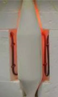
Insertion du four en fibre-céramique (figure 1)
Il s'agit d'une céramique d'oxyde renforcée par des fibres qui sépare les chambres de l'échantillon et du four et réduit les gradients de température. En outre, cet insert offre la possibilité de réaliser des atmosphères à faible teneur en oxygène ou, si nécessaire, d'autres gaz à l'intérieur.
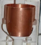
Un écran de protection thermique (figure 2) peut être utilisé en conjonction avec l'insert du four ou séparément. L'écran de protection thermique (figure 2) peut être placé au-dessus du support de flexion afin de réduire les gradients thermiques à l'intérieur et donc à proximité de l'échantillon.
La version simple en cuivre peut être utilisée jusqu'à max. 950°C. Au-delà de cette température, il convient d'utiliser une version en zirconium. Les deux versions sont des pièces d'usure, des matériaux dits "sacrificiels", car ils sont lentement consumés par l'OxydationL'oxydation peut décrire différents processus dans le contexte de l'analyse thermique.oxydation.
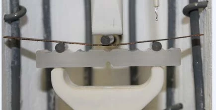
L'effet des différences perturbatrices des coefficients de dilatation thermique peut être éliminé par un support de flexion avec des roulements à rouleaux (saphir). Le support de flexion en saphir poli (figure 3) n'est soumis à aucune Transitions de phaseLe terme de transition de phase (ou changement de phase) est le plus souvent utilisé pour décrire les transitions entre les états solide, liquide et gazeux. transition de phase dans toute la plage de température concernée. En raison de sa structure monocristalline, il présente relativement peu de points susceptibles de réagir, c'est-à-dire qu'il est chimiquement inerte. C'est pourquoi le saphir convient parfaitement comme support de cintrage ! Les rouleaux polis, également en saphir, compensent les différentes dilatations thermiques en transformant la différence de déformation thermique entre l'échantillon et le support en un mouvement de rotation. La modification de la portée qui en résulte n'est en principe que marginale. En cas d'incompatibilité chimique entre les rouleaux et l'échantillon, les dommages peuvent être facilement réparés. Les rouleaux sont conçus comme des pièces d'usure et peuvent donc être remplacés facilement et rapidement. Différents matériaux de rouleaux sont disponibles comme alternative (par exemple, les rouleaux Si3N4 et SSiC).
Pour optimiser l'accouplement mécanique, un support monté sur cardan (figure 3, en haut au centre) peut être utilisé. Cette tige de poussée sert principalement à compenser le manque de parallélisme plan de l'échantillon. Cependant, elle est également efficace dans le cas d'une torsion de l'échantillon induite par la chaleur, car le support à cardan est toujours ajusté à la surface concernée.
Résultats des mesures
Le balayage de température effectué sous l'application de ces améliorations constructives sur
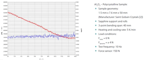
a) un échantillon d'Al2O3 polycristallin (figure 4),
b) un échantillon de saphir, également monocristal d'Al2O3 (figure 5) et
c) un composite C/CSiC (figure 6)
donnent les résultats suivants :
a) Al2O3 polycristallin
Les deux matériaux Al2O3 étudiés ont une structure fondamentalement différente. L'échantillon d'Al2O3 polycristallin se compose d'α-Al2O3 d'une pureté de 99,7% et est fritté. Il présente une phase vitreuse entourant les cristallites individuelles. À des températures supérieures à environ 1100°C, cette phase vitreuse intercristalline commence à se ramollir [2], ce qui se traduit par un processus de reptation dans le balayage de température (figure 4) et se caractérise par une forte baisse du module d'Young.
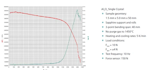
b) Saphir (monocristal)
Dans le cas du monocristal de saphir, les relations structurelles sont complètement différentes. Dans un monocristal, il n'y a évidemment pas de joints de grains ni de phases vitreuses. Il est donc également dépourvu d'effets de fluage, mais il est aussi beaucoup moins tolérant aux dommages. La baisse continue de |E*| et l'absence de signes d'effets de fluage sont prévisibles, tout comme les valeurs d'amortissement plus faibles par rapport à l'échantillon polycristallin (figure 5).
c) Fibre céramique C/SiC
Les composites C/SiC, fabriqués par l'université du Queensland, constituent un exemple d'utilisation d'une fibre céramique dans la DMA HT. Il s'agit d'un composite fabriqué par le procédé d'infiltration de polymère (PIP) avec un précurseur précéramique qui a ensuite été soumis à un processus de PyrolyseLa pyrolyse est la décomposition thermique de composés organiques dans une atmosphère inerte.pyrolyse (1600°C) sous atmosphère d'argon. Ce composite à 20 couches présente une disposition unidirectionnelle des fibres couche par couche avec une disposition alternée 0°/90° et une fraction volumique des fibres d'environ 50 % [1].
L'étude dynamique et mécanique a été réalisée dans les conditions de l'atmosphère environnante lors d'un balayage de température (chauffage) de la température ambiante à environ 1300°C, suivi directement d'un autre balayage de température de 1300°C à la température ambiante. Les vitesses de chauffage et de refroidissement étaient de 10 K/min. Pour l'acquisition des données de mesure, une force statique de 55 N est d'abord appliquée pour exciter l'échantillon (12,8 mm x 4,5 mm x 50 mm ; portée 44,5 mm) avec une force dynamique superposée d'une amplitude de 45 N à une fréquence d'essai de 3 Hz. Le résultat de la mesure est illustré à la figure 6.
Alors que pour les céramiques non renforcées telles que le SiC, le module d'Young diminue avec la température [3], les céramiques à fibres C/SiC présentent un module d'Young croissant. Les mesures RFDA (Resonant Frequency Damping Analysis) effectuées par le DLR de Stuttgart [4] sur les céramiques à fibres de C/SiC aboutissent au même résultat. Les résultats du DLR montrent également une augmentation du module d'Young avec l'augmentation de la température. Normalement, une augmentation du module avec la température n'est pas attendue et est donc quelque peu surprenante.
Dans les fibres céramiques, cependant, des causes microstructurelles peuvent expliquer l'augmentation du module d'Young dans les composites C/SiC sous l'effet de la chaleur. La PyrolyseLa pyrolyse est la décomposition thermique de composés organiques dans une atmosphère inerte.pyrolyse produit notamment un matériau déjà fissuré à température ambiante et soumis à des contraintes internes en raison des pertes de masse dans la partie matricielle. Avec l'augmentation de la température, les fissures se referment, c'est-à-dire que le flux de force passe de plus en plus directement par la matrice en raison de la plus grande expansion de celle-ci.
L'image des artefacts de déformation, qui trouvent leur origine dans la zone de contact entre l'échantillon et le support de flexion et qui peuvent être éliminés par des rouleaux et des paliers à cardan, doit être étendue au matériau des céramiques à fibres. Les fibres céramiques, telles que le C/SiC, sont sujettes à des fissures dues au processus de fabrication. Il est probable que les fissures, qui s'élargissent à basse température et se rétrécissent avec l'augmentation de la température, provoquent une déformation intrinsèque moindre en raison de la dilatation thermique. D'autres études sont prévues.
La dilatation thermique de la matrice - qui est généralement supérieure à celle de la teneur en fibres - fait que les fissures inhérentes aux échantillons, qui sont également de largeurs différentes, réduisent d'abord leur taille avec l'augmentation de la température, puis se referment éventuellement.
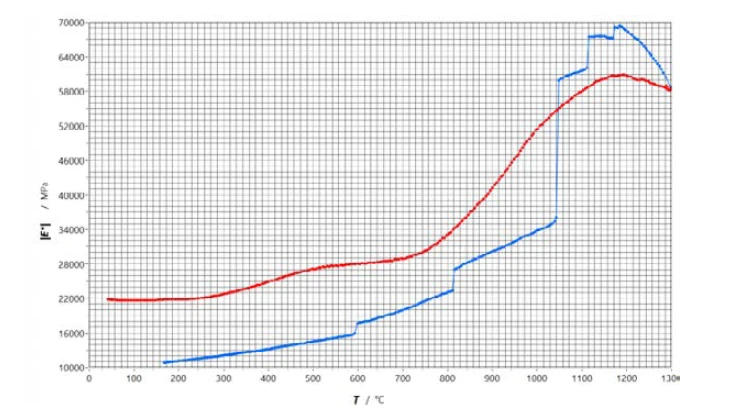
Avec l'augmentation de la température, la surestimation de la déformation diminue et le module d'Young augmente. Le module d'Young reflète donc le comportement réel du matériau fissuré en fonction de la température ! Dans l'atmosphère ambiante, l'OxydationL'oxydation peut décrire différents processus dans le contexte de l'analyse thermique.oxydation à la surface de la fissure peut également endommager les fibres. Ces conséquences deviennent visibles après une exposition prolongée par une diminution répétée du module, principalement pendant le refroidissement. Les fissures déjà agrandies par l'OxydationL'oxydation peut décrire différents processus dans le contexte de l'analyse thermique.oxydation précédente s'élargissent encore pendant le refroidissement. Si les dommages causés par l'OxydationL'oxydation peut décrire différents processus dans le contexte de l'analyse thermique.oxydation entraînent des fissures dans les segments de fibres, celles-ci peuvent être observées comme des sauts dans l'évolution du module d'Young.
Résumé
L'analyse dynamique et mécanique (DMA) peut déterminer de manière fiable et relativement rapide les propriétés élastiques telles que le module d'Young |E*| et l'amortissement tan δ dans des conditions proches de l'application avec les modifications de conception présentées. Des températures allant jusqu'à 1500°C sont possibles, de même que le choix de l'atmosphère dans la chambre d'échantillon (par exemple, conditions environnantes, gaz inerte ou environnement à faible teneur en oxygène). Ceci s'applique également aux fibres céramiques telles que le C/SiC. Le concepteur obtient ainsi des données mécaniques dépendant de la température jusqu'à 1500°C pour la conception de composants (structurels) en fibre-céramique dans des conditions d'application. En modifiant l'atmosphère de travail dans la chambre d'échantillon, il est également possible de modifier de manière ciblée le taux d'endommagement dû à l'OxydationL'oxydation peut décrire différents processus dans le contexte de l'analyse thermique.oxydation.