Introduction
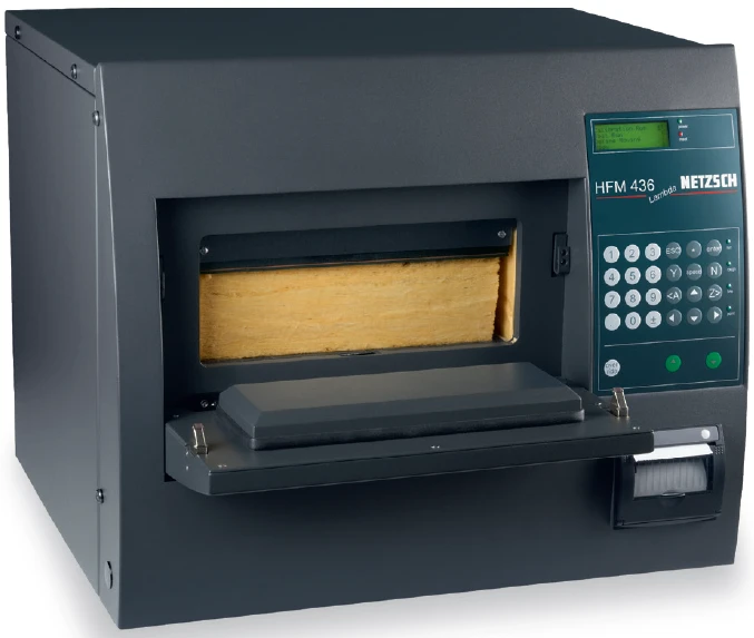
The heat flow meter (NETZSCH HFM 436 Lambda in Figure 1) method is most commonly applied to Thermal ConductivityThermal conductivity (λ with the unit W/(m•K)) describes the transport of energy – in the form of heat – through a body of mass as the result of a temperature gradient (see fig. 1). According to the second law of thermodynamics, heat always flows in the direction of the lower temperature.thermal conductivity measurements of insulating materials such as fiberglass, mineral fiber and polymer foams in the approximate range of 0.002 to 0.1 W/(m·K) and 20 to100 mm thickness. With special precautions regarding sample preparation, temperature measurement and instrument settings, the HFM method range can be extended to measurements of building materials such as concrete, masonry and wood, as well as plastics, composites and glass with Thermal ConductivityThermal conductivity (λ with the unit W/(m•K)) describes the transport of energy – in the form of heat – through a body of mass as the result of a temperature gradient (see fig. 1). According to the second law of thermodynamics, heat always flows in the direction of the lower temperature.thermal conductivity as high as 2 W/(m·K) and thermal resistance as low as 0.02 (m2·K)/W (see example in Table 1).

Table 1: Measurement of cement Thermal ConductivityThermal conductivity (λ with the unit W/(m•K)) describes the transport of energy – in the form of heat – through a body of mass as the result of a temperature gradient (see fig. 1). According to the second law of thermodynamics, heat always flows in the direction of the lower temperature.thermal conductivity using HFM 436/3 with instrumentation kit (rubber sheets and sample thermocouples)
| Sample | Sample thickness (mm) | Stack pressure | Temp. mean (°C) | Temp. Δ | Sample DensityThe mass density is defined as the ratio between mass and volume. density (kg/m3) | Thermal resistance (m²·(K/W)) | Thermal conductivity (W/(m·K)) | ||
|---|---|---|---|---|---|---|---|---|---|
| (PSI) | k(PA) | plates | samples | ||||||
| Cement | 76.25 | 2.0 | 13.8 | 26.1 | 19.2 | 14.3 | 1959 | 0.0617 | 1.24 |
With typical HFM measurements of insulating materials, the temperature difference across the sample (ΔT) as measured by the thermocouples embedded in the hot plate and cold plate surfaces can be used for the Thermal ConductivityThermal conductivity (λ with the unit W/(m•K)) describes the transport of energy – in the form of heat – through a body of mass as the result of a temperature gradient (see fig. 1). According to the second law of thermodynamics, heat always flows in the direction of the lower temperature.thermal conductivity calculation. Although there is always a small thermal resistance and temperature drop present at the plate to sample interfaces, they can be neglected compared to the much larger sample thermal resistance and ΔT. For compressible insulating materials, good thermal contact is ensured if the sample is compressed slightly by the plates. For more rigid materials such as plastic foam, these contact resistances can still be neglected as long as the sample surfaces are flat and parallel and sufficient pressure is applied by the HFM plates. For higher Thermal ConductivityThermal conductivity (λ with the unit W/(m•K)) describes the transport of energy – in the form of heat – through a body of mass as the result of a temperature gradient (see fig. 1). According to the second law of thermodynamics, heat always flows in the direction of the lower temperature.thermal conductivity materials, generally with thermal conductivity > 0.5 W/(m·K) and thermal resistance < 0.1 (m2·K)/W, the plate to sample contact resistances can no longer be neglected. Also, since these materials are generally rigid and incompressible and may have rough surfaces, thermal contact with the HFM plates may be even further reduced by gaps and air films. To overcome these effects, sample surface mounted thermocouples and rubber interface sheets are employed as described.
Sample Preparation
To give sufficient sample thermal resistance and ΔT, a minimum sample thickness of 50 mm is recommended. Maximum thickness is approximately 90 mm to allow space for the interface pads and installation and removal of the sample.
Prepare the sample surfaces in contact with the plates to be as smooth as possible and flat and parallel within approximately 0.3 mm. While this may be challenging for many building materials such as concrete, it is necessary for good thermal contact with the HFM plates even when these special procedures are followed.
Before installation in the HFM, the sample thickness should be carefully measured in several locations near the central metering area and the average calculated.
HFM Calibration
A normal calibration using the supplied fiberglass board standard is sufficient. It is not necessary to calibrate using the sample thermocouples and interface sheets or with a higher thermal conductivity standard sample. Testing has shown that the heat flux transducer calibration using the fiberglass board standard is valid over a large range of thermal resistance.
Procedures − NETZSCH HFM 436/3 with Optional InstrumentationKit
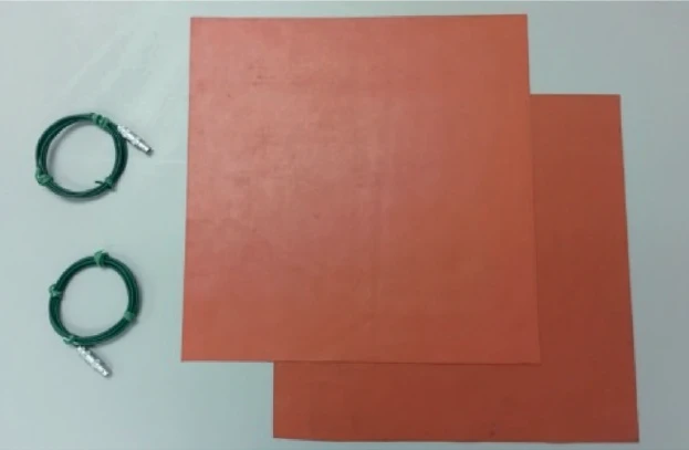
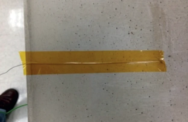
- Two thermocouples and two silicone rubber interface sheets are supplied (Figure 2). Mark the center point of each sample surface, lay the upper and lower thermocouple probes with the end placed near the center mark and tape in place as shown in Figure 3.
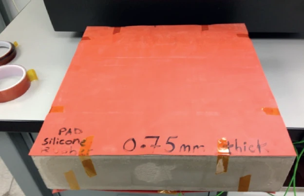
- Place the rubber sheets on each side of the sample over the surface thermocouples and tape them in position around the sample edges as shown in Figure 4. The tape will keep the sheets from shifting or folding during sample loading.
- Load the sample in the HFM chamber and lower the plate until it stops automatically (maximum plate load applied). If using the optional stack loading feature, a plate pressure of about 2 PSI (about 4 kPa) is recommended to improve thermal contact.
- Plug the upper sample thermocouple connector into the left position (Instrumentation Kit) and the lower sample thermocouple connector into the right position.
- In Q-Lab software
For sample definition “User Thickness” must be selected and the sample thickness in cm entered in the window. The sample thickness will be used to calculate thermal conductivity. Note that the Gauge Thickness now includes the thickness of the rubber interface sheets. Depending on the thermal resistance of the sample a smaller temperature Δ will normally need to be defined to avoid saturation of the heat flux transducer readings, Q Upper and Q Lower. For samples such as concrete (thickness of 50 mm, thermal conductivity > 1 W/(m·K)), a Δ of 10 K or less (across the sample) is typically required. The Δ must be selected to keep the Q Upper and Q Lower readings at equilibrium at or below approximately 32000 uV. This may require setting several setpoints with different Δ when testing unknown samples. The minimum recommended Δ is approximately 4 K.


